Connecting the PC to the outside world.
[Testing ports and interfacing][Ham-Comp notes]
NOTE:
This article has been constructed like this:-
A. What’s it for? (What is its function?)
B. Why is it like this? (What made the design like this?)
C. How can we (Radio Amateurs) use it?
D. I think it’s broken, how can I test it?
In the PC, there are several interfaces and a few that connect to the outside world. The few that connect to a socket/plug for you to connect something to are: -
The Joystick Port
The Serial Port
The Parallel Port and additional printer ports
The Speaker (Noise maker)
The Keyboard socket
The Sound card interface
The VGA adapter ‘feature’ connector
Contents
Connecting the PC to the outside world.
Test Software for the serial (RS232) Port
The Centronics Printer Port adapter
The Joystick Port
A
This port is used to provide positional and contact closure information to a program (usually a game) running on the PC. The Joystick section is a pair of 100k potentiometers aligned at ninety degrees, so that a steering arm or ‘stick’ can move forward and backward or side-to-side. These potentiometers are electrically connected from the five-volt supply to a timer circuit input. This allows you to fly a simulated aeroplane or steer some other object inside the software. It really is a pair of crude/simple analogue to digital converters. The processor simply times the timer’s output with the clock pulses and counts the result. When the potentiometer is low resistance the time is short, giving fewer clock pulses to count. When the resistance is larger, the timer takes longer to timeout and more clock pulses are counted.
The other four inputs on this port are simply button sensors. When the contact of the button closes, the input goes low and this can be read from the port as a status.
B
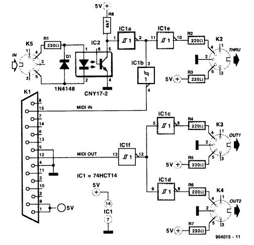
Originally it was a very simple circuit. Consisting of 555 or 558 timers and some TTL chips. As the sophisticated sound cards arrived the ports function was added to the sound card. It also provides MIDI interfacing to a host of electronic musical instruments. It can supply a 5 Volts supply for low current usage. The early circuits could be modified for other purposes but the sound card interfaces will not allow this.
C
Uses for Amateurs include slow-scan television, sensing or powering small circuits for other interfacing.
D
Connecting a 15-pin connector and push buttons will let you check the logic. The joystick analogue section is not so easy to check without a real joystick or four 100k potentiometers.
If you wish to connect musical instruments to the joystick interface, here is a circuit: -
The RS232 serial port
A
The serial port which complies with the ‘Recommended Standard number 232’ is used to communicate one bit at a time with another device. The device could be another computer, an electronic device or another interface to communicate with the outside world.
B
The original serial adapter card was slow and not very sophisticated. The later cards for the 80486-type processor were capable of much higher speeds. The outside world interface was quite tolerant of the voltage levels supplied to it by external equipment. However later models ‘tightened’ up on the RS232 specification-giving rise to unreliable interfacing with amateur equipment.
C
The serial port can be used for a multitude of functions. It has several control logic pin connections, which can be used to turn on or off external devices. Also the serial data input/output can be transmitted asynchronously at very slow rates to a maximum of 115,000 bits per second.
D
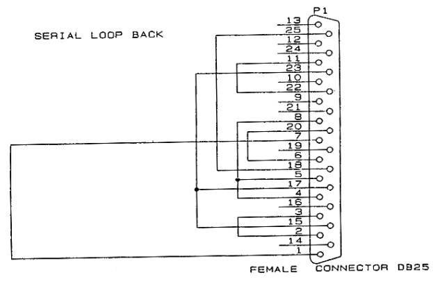
To check the serial port fully requires a ‘loop-back’ connector plug. This can be a 9 pin or 25 pin female plug wired as shown below. Also some simple software is needed to ‘exercise’ the port fully. This can be written in Quick Basic, C, assembler or any other language you prefer.
To correctly check the operation of the UART chip, an interrupt should be used to transmit and receive a test stream of data. This can be done in most DOS based languages without too much interference from the operating system.
Test Software for the serial (RS232) Port
'
' Equipment Check - (C) Copyright 1992 to 1996 John Brock
'
' Equip.bas - is meant as a demonstration program, so it can be used for
' demonstrating the access of the hardware. It carries out tests on the
' serial ports if present and the parallel printer ports if present.
' This program does not check Com3 or Com4, Equip.exe does though.
'
' Use it and adapt it - JB
'
DEFINT A-Z
DECLARE FUNCTION adapter ()
DECLARE SUB TextCentre (Txt$, L%)
DECLARE FUNCTION GetBaud$ (Port%)
'--
CONST True = -1
CONST False = 0
CONST TEST = True
'--------------------- check on screen adapter type ...
CONST MDP = 1, CGA = 2, HGC = 3, EGA = 4, VGA = 5, MCGA = 6, OLI = 7
DIM ScrnType$(10)
ScrnType$(1) = "Mono display adapter"
ScrnType$(2) = "Colour Graphics adapter"
ScrnType$(3) = "Hercules Graphics adapter"
ScrnType$(4) = "Extended Graphics adapter"
ScrnType$(5) = "Video Graphics Array adapter"
ScrnType$(6) = "Multi-Colour Graphics adapter"
ScrnType$(7) = "Olivetti screen adapter"
ScrnType$(8) = "Unknown"
ScrnType$(9) = "Unknown"
ScrnType$(10) = "Unknown"
REM *** NOTE this routine clears the current screen ***
Ad = adapter
' reset error handling
ON ERROR GOTO ErrHandler2
' define the Segment as &H40 for access to the equipment info storage area
DEF SEG = &H40
'-- White on Blue
COLOR 7, 1
CLS
M$ = " Equipment Check for Communications & Screen Type "
TextCentre M$, 1
M$ = " Copyright (C) 1992 John Brock Computing Services "
TextCentre M$, 25
M$ = "--- Communication ports ---"
TextCentre M$, 3
IF PEEK(0) + 256 * PEEK(1) <> 0 THEN
PRINT "Communications Port 1 is at address : ";
A& = 256 * PEEK(1) + PEEK(0)
PRINT HEX$(A&) + "h",
PRINT "Port 1 set to "; GetBaud$(CSNG(A&)) + "bps"
C1 = True
ELSE
PRINT "Communications Port 1 does not exist"
C1 = False
END IF
LOCATE 6, 1
IF PEEK(2) + 256 * PEEK(3) <> 0 THEN
PRINT "Communications Port 2 is at address : ";
A& = 256 * PEEK(3) + PEEK(2)
PRINT HEX$(A&) + "h",
PRINT "Port 2 set to "; GetBaud$(CSNG(A&)) + "bps"
C2 = True
ELSE
PRINT "Communications Port 2 does not exist"
C2 = False
END IF
LOCATE 8, 1
IF PEEK(4) + 256 * PEEK(5) <> 0 THEN
PRINT "Communications Port 3 is at address : ";
'- remember that intel stores numbers back to front
A& = 256 * PEEK(5) + PEEK(4)
PRINT HEX$(A&) + "h",
PRINT "Port 3 set to "; GetBaud$(CSNG(A&)) + "bps"
C3 = True
ELSE
PRINT "Communications Port 3 does not exist"
END IF
LOCATE 10, 1
IF PEEK(6) + 256 * PEEK(7) <> 0 THEN
PRINT "Communications Port 4 is at address : ";
A& = 256 * PEEK(7) + PEEK(6)
PRINT HEX$(A&) + "h",
PRINT "Port 4 set to "; GetBaud$(CSNG(A&)) + "bps"
C4 = True
ELSE
PRINT "Communications Port 4 does not exist"
END IF
IF C1 THEN
'---------------------- Test Communications on Port 1 ---------------------
OUT &H3FC, 16 ' switch on loop back inside UART
'
IF INP(&H3FC) = 16 THEN
M$ = "Loop check on Com1"
TextCentre M$, 24
END IF
'
LOCATE 5, 1
FOR D = 65 TO (65 + 25)
OUT &H3F8, D
'
' wait a few ticks
FOR t = 1 TO 10000: NEXT
IF (INP(&H3FD) AND 1) = 1 THEN
PRINT CHR$(INP(&H3F8)); " ";
END IF
NEXT D
OUT &H3FC, 0 ' switch off loop back
10 '
' Now test sending a chr out the port and back in
'
R = FREEFILE
OPEN "Com1:1200,N,8" FOR RANDOM AS #R
PRINT #R, "*";
FOR t = 1 TO 5000
IF NOT EOF(R) THEN
PRINT INPUT$(1, #R);
END IF
NEXT t
Cont1:
CLOSE #R
M$ = "RS232 Com1 checked."
TextCentre M$, 24
END IF
IF C2 THEN
'---------------------- Test Communications on Port 2 ---------------------
OUT &H2FC, 16
IF INP(&H2FC) = 16 THEN
M$ = "Loop check on Com2"
TextCentre M$, 24
END IF
LOCATE 7, 1
FOR D = 65 TO 65 + 25
OUT &H2F8, D
FOR t = 1 TO 10000: NEXT
'
'
IF (INP(&H2FD) AND 1) = 1 THEN
PRINT CHR$(INP(&H2F8)); " ";
END IF
NEXT D
'
OUT &H2FC, 0 ' switch off loop back
20 '
' Now test sending a character out the port and back in
'
R = FREEFILE
OPEN "Com2:1200,N,8" FOR RANDOM AS #R
PRINT #R, "*";
FOR t = 1 TO 5000
IF NOT EOF(R) THEN
PRINT INPUT$(1, #R);
END IF
NEXT t
Cont2:
CLOSE #R
M$ = "RS232 Com2 checked."
TextCentre M$, 24
END IF
' Now check for printer ports
M$ = "--- Parallel printer ports ---"
TextCentre M$, 13
LOCATE 14, 1
IF PEEK(8) + 256 * PEEK(9) <> 0 THEN
PRINT "Parallel printer port LPT1 is at address : ";
Port$ = HEX$(PEEK(9)) + HEX$(PEEK(8))
PRINT Port$; "h";
' test it by writing a value to it and reading it back.
Port = VAL("&H" + Port$) ' treat the port as hexadecimal
OUT Port, &HAA
IF INP(Port) = &HAA THEN
OUT Port, &H55
IF INP(Port) = &H55 THEN
M$ = "Printer port Lpt1 checked."
TextCentre M$, 24
END IF
END IF
ELSE
PRINT "Parallel printer port LPT1 does not exist"
END IF
LOCATE 15, 1
IF PEEK(10) + 256 * PEEK(11) <> 0 THEN
PRINT "Parallel printer port LPT2 is at address : ";
Port$ = HEX$(PEEK(11)) + HEX$(PEEK(10))
' test it by writing a value to it and reading it back.
PRINT Port$; "h";
' test it by writing a value to it and reading it back.
Port = VAL("&H" + Port$) ' treat the port as hexadecimal
OUT Port, &HAA
IF INP(Port) = &HAA THEN
OUT Port, &H55
IF INP(Port) = &H55 THEN
M$ = "Printer port Lpt2 checked."
TextCentre M$, 24
END IF
END IF
ELSE
PRINT "Parallel printer port LPT2 does not exist"
END IF
LOCATE 16, 1
IF PEEK(12) + 256 * PEEK(13) <> 0 THEN
PRINT "Parallel printer port LPT3 is at address : ";
Port$ = HEX$(PEEK(13)) + HEX$(PEEK(14))
' test it by writing a value to it and reading it back.
PRINT Port$; "h";
' test it by writing a value to it and reading it back.
Port = VAL("&H" + Port$) ' treat the port as hexadecimal
OUT Port, &HAA
IF INP(Port) = &HAA THEN
OUT Port, &H55
IF INP(Port) = &H55 THEN
M$ = "Printer port Lpt3 checked."
TextCentre M$, 24
END IF
END IF
ELSE
PRINT "Parallel printer port LPT3 does not exist"
END IF
' reset the data segement to the default
DEF SEG
'--------------------------- report adapter found -------------------------
M$ = "--- Display adapter ---"
TextCentre M$, 18
M$ = "Adapter type : " + ScrnType$(Ad)
TextCentre M$, 19
LOCATE 25, 70
END ' End of program.
'--- Branch here when test fails and change test result.
Handler:
Mode(ModeNumber) = False
RESUME NEXT
ErrHandler2:
'--- we come here when the external loopback fails.
IF ERL = 10 THEN RESUME Cont1
IF ERL = 20 THEN RESUME Cont2
PRINT ERL, ERR
END
'================================= Adapter ================================
' To determine the adapter, try every screen mode and see which one works.
'==========================================================================
FUNCTION adapter
ON ERROR GOTO Handler
' Use an array to keep track of our test results
DIM Mode(1 TO 13)
' Try screen modes and see which work.
FOR ModeNumber = 1 TO 13
' Assume the test works unless you get an error.
Mode(ModeNumber) = True
SCREEN ModeNumber
NEXT ModeNumber
' Reset the screen after testing it.
SCREEN 0, 0
WIDTH 80
' Using test results figure out which adapter is out there.
' Tell operator which one he has.
' (See tables in SCREEN section of BASIC Language Reference
' to undertand why this logic works.)
IF Mode(13) THEN
IF Mode(7) THEN
UseableModes$ = "0-2, 7-13."
adapter = VGA
ELSE
UseableModes$ = "0-2, 11 and 13."
adapter = MCGA
END IF
ELSE
IF Mode(7) THEN
UseableModes$ = "0-2, 7-10."
adapter = EGA
ELSE
IF Mode(3) THEN
UseableModes$ = "3."
adapter = HGC
END IF
IF Mode(4) THEN
UseableModes$ = "4."
adapter = OLI
END IF
IF Mode(1) THEN
UseableModes$ = "0-2."
adapter = CGA
ELSE
UseableMode$ = "0."
adapter = MDP
END IF
END IF
END IF
END FUNCTION
'================================ GetBaud =================================
' GetBaud returns the current baud rate in Baud$
' Port should be set to &h3f8 or &h2f8 for com1: and com2:, respectively.
'==========================================================================
FUNCTION GetBaud$ (Port)
Dlab = INP(Port + 3)
Dlab = Dlab OR 128
OUT Port + 3, Dlab ' Set Divisor Latch Access Bit on
lsb = INP(Port) ' read least significant byte of divisor
msb = INP(Port + 1) ' read most significant byte of divisor
Divisor = ((msb * 256) + lsb) * 16 'clock is prescaled by 16
Dlab = Dlab AND &H7F ' knock down bit 7
OUT Port + 3, Dlab ' Set Divisor Latch Access Bit off
Baud$ = LTRIM$(STR$(1843200! / Divisor))
' return the string
GetBaud$ = Baud$
END FUNCTION
'=============================== TextCentre ===============================
' print centred text string on specified line L
'==========================================================================
SUB TextCentre (Txt$, L)
TL = LEN(Txt$)
LOCATE L, (40 - (TL \ 2))
PRINT Txt$;
END SUB
The Centronics Printer Port adapter
A
This port was originally only for connection to the printer. It only ‘talked’ in one direction and sensed the printer’s status on a few pins. It wasn’t even interrupt driven, as the port’s hardware was considered unreliable. Later models feature bi-directional usage and DMA transfers of high-speed data.
B
Simple TTL integrated circuits were used as the connection was to a similar device also with TTL circuitry. Moderately high speeds of data transfer were achieved over cables of less than 10 metres.
C
This port has been used by Radio Amateurs for a multitude of functions. It has been used to orientate aerial arrays, tune up valve finals and even print!
D
Checking the port and its hardware again requires both a ‘loop-back’ connector show below as well as some simple software. I wrote the Quick Basic program recently to provide a skeletal test program for you to adapt as you see fit.
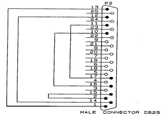
Printer Port Pin-out
Connecting two PC’s together
Program to test printer ports
'
' Lpt-Test.bas - a program to use the
loop-back connector to
' to check the working of the printer port's
' hardware.
'
'option explicit
'
' Method:
'
1) Check for the BIOS
found/tested ports in memory.
'
2) For each port, check the
outputting and inputting of data.
'
3) Tell user at all times
what is going on.
'
4) Report all 'broken'
hardware.
'
DECLARE FUNCTION Bin$ (x AS INTEGER)
DECLARE SUB WaitForAKey ()
'-- clear the screen
COLOR 7, 1
CLS
'-- Tell user what is happening....
PRINT "[Lpt-Test (C) JB for HamComp
2005-11-26]"
PRINT "This is a printer port tester
program."
PRINT "It will find the printer ports in
your PC. If you have connected a simple"
PRINT "loopback connector to the printer
port, it will test the individual ports "
PRINT "and bits in sequence. You may
press a key when ready."
'--
WaitForAKey
'-- set the segment to the BIOS data area
DEF SEG = &H40
'--
DIM LpPorts(4) AS STRING * 5
'--
p = 1
'--
PRINT "Printer ports found."
'--
FOR n = 8 TO 14 STEP 2
'--
PRINT "Lpt" + LTRIM$(STR$(p)),
'--
PRINT RIGHT$("0000" + HEX$(PEEK(n + 1)) + HEX$(PEEK(n)), 4) +
"h"
'--
LpPorts(p) = RIGHT$("0000" + HEX$(PEEK(n + 1)) +
HEX$(PEEK(n)), 4) + "h"
'--
p
= p + 1
'--
NEXT n
'-- put a line between
PRINT
'-- Now check the ports
FOR port = 1 TO 4
'-- check the port
IF
LpPorts(port) <> "" THEN
'-- valid port address
p = VAL("&H" + LpPorts(port))
'-- what's AA ?, its a bit pattern of 10101010
OUT p, &HAA
'-- now read it back and compare it
IF INP(p) = &HAA THEN
'-- what's 55 ?, the opposite of AA, 01010101
OUT p, &H55
'-- now read it back and compare it
IF INP(p) = &H55 THEN
'--
PRINT "Printer port Lpt" +
LTRIM$(STR$(port));
PRINT " is functional."
'--
PRINT "Now checking loopback connection and
port."
'-- output to the control port
OUT p + 2, 0
'-- reset
OUT p, 0
PRINT INP(p + 1) AND 8, Bin$(INP(p + 1) AND 8)
OUT p, 1
PRINT INP(p + 1) AND 8, Bin$(INP(p + 1) AND 8)
'-- set bit 0
OUT p + 2, 1
PRINT INP(p + 1) AND 16,
Bin$(INP(p + 1) AND 16)
OUT p + 2, 0
PRINT INP(p + 1) AND 16, Bin$(INP(p + 1) AND 16)
'-- set bit 1
OUT p + 2, 2
PRINT INP(p + 1) AND 32, Bin$(INP(p + 1) AND 32)
OUT p + 2, 0
PRINT INP(p + 1) AND 32, Bin$(INP(p + 1) AND 32)
'-- set bit 2
OUT p + 2, 0
PRINT INP(p + 1) AND 64, Bin$(INP(p + 1) AND 64)
OUT p + 2, 4
PRINT INP(p + 1) AND 64, Bin$(INP(p + 1) AND 64)
'-- set bit 3
OUT p + 2, 0
PRINT INP(p + 1) AND 128, Bin$(INP(p + 1) AND 128)
OUT p + 2, 8
PRINT INP(p + 1) AND 128, Bin$(INP(p + 1) AND 128)
'
PRINT "Pattern should be 0, 8, 0, 16, 0, 32,
0, 64, 0, 128. ";
PRINT "Press a key when ready...";
'--
WaitForAKey
END IF
END IF
ELSE
'--
PRINT "Printer port Lpt" + LTRIM$(STR$(port));
PRINT " is NOT functional."
END IF
'--
NEXT port
'--
FUNCTION Bin$ (x AS INTEGER)
'
' Convert an integer to a binary string of
1's and 0's
'
DIM strRet
AS STRING * 16
DIM p
AS INTEGER
DIM bit
AS INTEGER
'--
FOR p = 15 TO 0 STEP -1
'--
bit = x AND 2 ^ p
'--
SELECT CASE bit
CASE 0
MID$(strRet, 16 - p) = "0"
CASE 1, 2, 4, 8, 16, 32, 64, 128
MID$(strRet, 16 - p) = "1"
CASE 256, 512, 1024, 2048, 4096, 8192, 16384
MID$(strRet, 16 - p) = "1"
END SELECT
'--
NEXT p
'--
Bin$ = strRet
'--
END FUNCTION
SUB WaitForAKey
'
' wait for a key pressed
'
DIM I$
I$ = ""
WHILE I$ = ""
I$
= INKEY$
WEND
'
END SUB